Air Density Correction and SuperFlow Flowbenches
October 23, 2020
There Is No Air Density Correction
There is no air density correction required to adjust for different atmospheric conditions when testing. This is the concept that causes concern for many people. Doesn’t the flow through an orifice change with changing air density? Yes, it does. Well, why doesn’t the flow bench perform a calculation to compensate for the changing air density? Read on to understand why there is no correction, and why this is appropriate to do.
Why There Is No Correction
The simple answer to this is that our flow benches are ratiometric measuring devices. In other words, the density of the air in the room when you perform a test does affect the flow, but it affects both the test article as well as the orifice plate internal to the flow bench by the same amount and
this effect is automatically accounted for in the way that the flow measurement is calculated. If the air density causes the mass flow to go up by 10%, then the flow bench simply flows more, but it still measures the flow as if the air density was at 60°F and 29.92 inches of Hg. This correction is not done in software, instead it is a natural consequence of the mechanics of the flowbench. The flowbench only looks at pressures across the test article and across the orifice internal to the bench. If you apply 10% more differential pressure across the test article, then there will be the same 10% increase in differential pressure across the orifice plate. If the density of the air changes and therefore the differential pressure across the test article changes, then the differential pressure across the internal orifice changes a similar amount. If the differential pressure at the test article goes up a certain amount, then the FlowCom will adjust the blower speed to bring the test article differential pressure back to the original set point (usually 25” H20), which will then bring the orifice plate differential pressure back to its earlier reading as well.
Technically speaking, the flow bench does not measure flow, it measures differential pressure across the internal orifice and then calculates the flow as if the flow bench was in a room full of 60°F and 29.92” Hg air with the same differential pressure. You would be correct in your thinking that the flow would change as a result of the density change, but the key point here is that the flow bench does not measure flow, it measures the pressure across the orifice internal to the bench, and the pressure across the orifice changes in proportion to the change in air density such that the calculated flow number is constant. If you really want to investigate this using flow calculations, then a good reference is the ASME (American Society for Mechanical Engineer) MFC-3M-2004 publication. According to equation 2-1 in this publication, the flow through a sharp edged orifice is:
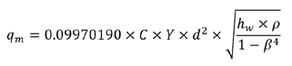
- qm = mass flow in lbm/sec
- C = Discharge Coefficient
- Y = Expansibility Factor
- d = throat diameter of orifice in inches
- hw = Differential Pressure across orifice in inches of water
- p = upstream air density in lbm/ft^3
- B = Beta (throat diameter ratio of orifice to tube)
If we use the above equation, but consider the flow through two different orifices that are in series with each other, we get the following equation.
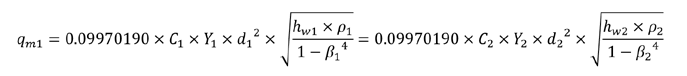
The mass flow through the first orifice must be equal to the mass flow through the second orifice or else mass is being accumulated somewhere (or there is leakage, but we will assume zero leakage for this analysis).
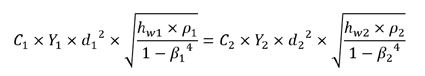
Since the expansibility factor Y and the 0.09970190 terms are essentially constants on both sides of the equation, we can simplify it to:
The terms C1, C2, D1, D2, B1 and B2 terms do not change with changes in atmospheric conditions, and the above equation can be simplified even further to:
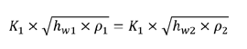
At low speeds it is appropriate to assume that air is incompressible, and p1 = p2. This is true at speeds below 100 m/s, which is roughly the equivalent velocity of escaping air with a differential pressure of 25 inches of water. At speeds above this, there are some air density corrections, but the amount of the correction is far smaller than the actual air density change. Using this incompressible assumption, we can now define the differential pressure at the orifice plate as a function of the differential pressure at the test article:
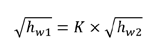
As you can see, this equation has no air density reference. So, if you have a test pressure of 25 inches of H20, the orifice pressure is simply a multiple of this, regardless of the air density. To be absolutely technically correct, there are some minor factors such as Expansibility and Discharge Coefficient that do change with air density changes, but these effects are extremely small, usually much less than 0.25% so it is normally safe to ignore these effects as the accuracy of the pressure measurement is typically less accurate.
