How To Determine The Total Engine and Dynamometer Inertia
February 8, 2021
An engine dynamometer provides for testing an engine when it is mounted to a power absorber. The torque along with speed (RPM) is measured and the horsepower is calculated by the testing system. The power absorber on most dynamometers is either a water brake, an electric motor, or an eddy current. These types of power absorbers apply a controlled load to the engine and measure the resultant torque with a strain gage or load cell. Torque combined with RPM calculates horsepower. Horsepower = Torque x RPM / 5,252
There are two types of tests performed on a dynamometer, an acceleration or sweep test and a steady state test. Most performance dynamometers operators prefer a sweep test as it provides a broader representation of the torque/power curve, and it is quicker.
However, there are two factors that affect the horsepower output of an engine that is not measured by the load cell. One is the frictional losses. Mechanical friction in the engine and aerodynamic friction in the coupling to the dynamometer reduces the power transferred to the dynamometer. But since the focus of the test is power at the flywheel (FHP), the internal losses are of little concern (except for companies that make bearings and oil), and the aerodynamic losses are very minimal.
The other factor is inertia. According to Newton’s second law of motion, the rate of change of the momentum of a mass is directly proportional to the force applied (F=mA). As applied to a sweep test on a dynamometer, it takes power to accelerate the moving parts of an engine and the dynamometer. This power is unmeasured by the dynamometer. If this power was known then it could be added to the power measured by the load cell to give a total power result.
To measure this power requires knowing the acceleration rate and the inertia mass of the moving components. The acceleration rate is easy to calculate with RPM and a timer. Or just by using the acceleration rate selected by the operator. But the inertia is unknown except in rare circumstances.
The good news is that inertia can be determined using a SuperFlow engine dynamometer because inertia power is calculated by WinDyn. We just need to know the engine inertia so the numbers are correct.
First a steady state test is performed. A steady state test is when the engine is held under load at a fixed speed. When doing this the acceleration is zero and therefore no force is taken up by acceleration. At steady state all the torque produced by the engine is measured by the load cell and applied to the calculation of horsepower.
Then an acceleration test is performed and the data compared to the steady state data. The image below shows the differences in power output of an engine in a step test and in a sweep test with no inertia compensation. This graph shows that the higher the acceleration rate the more power that is unmeasured.
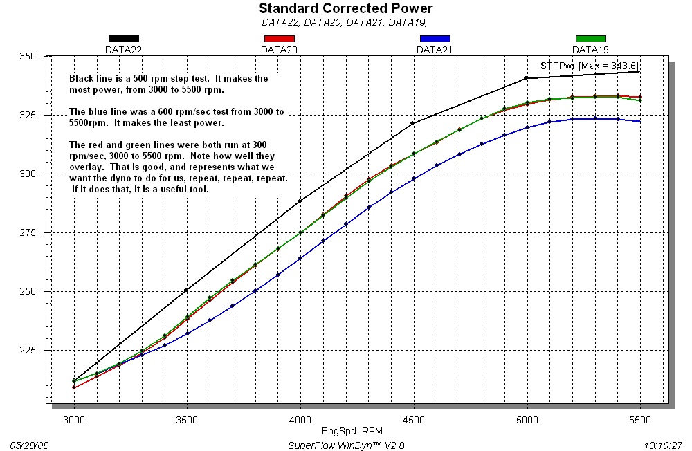
The step test is a form of Steady State where the engine is held at a fixed speed for a few seconds after which one data point is recorded. Then the dyno releases some of the load to “step” the rpm to the next data point. Again, because the acceleration at each data point is zero, all the torque produced by the engine is measured by the load cell.
In the WinDyn software there is a Specification channel named Inrtia. This value represents the total inertia of all moving parts on the engine and dynamometer. This entered value combined with the acceleration rate will provide a close approximation of the torque used in the acceleration. This torque is then added to the measured torque in the EngTrq channel.
Another Specification channel named InrCor is used to control the use of the inertia in EngTrq. A value of “1” in this channel turns ON the inertia correlation and a “0” turns it OFF.
The Procedure
NOTE: All test are performed at wide open throttle (WOT). Attempts should be made to maintain a constant oil and coolant temperature.
- Start by doing an acceleration test with InrCor set to zero (0)
- Determine the RPM at which peak power or torque occurs.
- Leave the InrCor at zero (0) and with the engine warm do a steady state test at the peak power or torque RPM, recording data for at least ten seconds.
- Use the Stored Viewer Column Averaging feature to determine the average horsepower or torque at the steady state RPM (this is the target).
- Set InrCor to one (1) and make a note on what the entered Inrtia value is.
- Run an acceleration test at speeds that encompass the desired peak (power or torque) value at a rpm/sec Rate that you will likely use for this engine.
- Open and plot the acceleration test.
- Overlay the steady state test.
- Ideally, the line for the acceleration test should intersect the average point of the steady state test.
- If it does not, change the Inrtia value up or down as necessary and run another acceleration test.
- Repeat until satisfied.
The final result will be the inertia of all the moving parts on the engine and dynamometer.
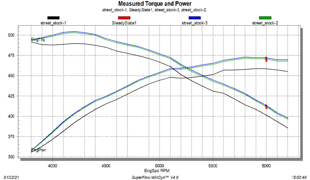
The image below is an example taken from a SuperFlow PowerMark dyno.
- The Black line is a 400 rpm/sec acceleration test with the InrCor turned OFF.
- The large Red dot is a steady state test at 6000 rpm averaged at 470HP.
- The Blue line is the acceleration test with Inrtia set at the default value of 0.4.
- The Green line is the acceleration test with Inrtia value set at 0.35.