Understanding and Working with SuperFlow Flowbenches
May 12, 2021
Overview
An engine makes power by moving air and fuel into and out of it. The more of both it can move, and the faster it can do it, the more power the engine makes. In theory it’s pretty simple but in reality it’s more complicated.
There are thousands of factors that effect not only how much air, but also the quality of that air, that gets into an engine. The most restrictive, and therefore the most critical factors, are the cylinder head intake and exhaust ports. That’s why so much thought and design must go into a cylinder head for each application.
We don’t have room here to illustrate how to maximize a cylinder head’s effectiveness by port design and shaping—that information could easily fill several hard-bound books. Rather, let’s talk about how to measure airflow in and out of a combustion chamber using a flowbench.
Measuring Airflow
New cylinder heads rated by several measurements but one of the most important to consider is cubic feet per minute (CFM) of air that can flow in both the intake and exhaust ports. The CFM rating should be tailored to the engine’s desired flow rate and power level, which could fill yet another book. The flowbench is a tool that lets you check what that flow is. Let’s say you performed a home porting job on your heads (yet another book) and want to see how much, if any, you improved flow. The flowbench will tell you.
SuperFlow offers a variety of flowbenches to fit the needs of race shops, garages and parts manufacturers.
“The main reason for the different flowbench sizes is to match the flow requirement of different heads,” sums up Mike Giles, former marketing manager at SuperFlow. “You don’t need the highest capacity bench to flow a motorcycle head.”
SuperFlow benches range from flowing up 160 cfm at 10 inches of water to 1,100 cfm at 25 inches. Again, check out the video to learn more about each flowbench.
One of the key features for SuperFlow benches is the FlowCom measurement system that does away with manual reading of a manometer. Some veteran engine builders may prefer the old method of watching the water levels, but there are numerous advantages to the new system.
“Some guys don’t trust computers,” says Giles. “They like using manometers because they can see it. From a technical standpoint, the FlowCom is much more accurate.”
The main problem with a manometer is that the readings can change depending on the viewing angle of the meniscus.
“That’s especially true on smaller benches where the scale isn’t as large,” adds Giles.
Another benefit of a computerized measurement system is cost.
“Believe it or not, it’s more affordable to produce the FlowCom than use a manometer,” says Giles. “Also, with the computer you get additional features, such as no more lookup tables. The numbers that read out are already corrected.”
Power Automedia recently obtained a SuperFlow SF-750 flowbench for the shop and is already putting it to good use on projects. This story will show how to use it, and then how to interpret the data using the help of Curtis Boggs from Race Flow Development (RFD) in Virginia Beach, VA.
How A Flowbench Works
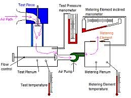
A flowbench is not that complicated in that all it does it push or pull air through an orifice, with that orifice most commonly being a cylinder head. It then measures the amount and velocity (or pressure) of the air that’s being moved through the system, and gives the user the data. But moving enough air to flow a racing cylinder head is not easy, hence the more airflow required, the bigger and more complicated (read expensive) the flowbench. Shown here is a simplified illustration of how a flowbench works.
SuperFlow has several different models of flowbenches. The SuperFlow SF-750 outlined here is a great bench for even a big engine shop; SuperFlow calls it “the new standard in digital flow testing, with more capacity than its predecessor, the SF-600, and increased accuracy with digital measurements.” It’ll flow 660 CFM at 25 inches of water and comes standard with SuperFlow’s FlowCom™ digital airflow measurement system for accurate, repeatable and fast testing.
FlowCom™ ensures accurate digital airflow measurement and control by automatically measuring test pressure and temperature; then presenting corrected flow data on the easy-to-read, precision display. This saves users considerable time when compared with standard manometer type benches that require users to make calculations to achieve corrected flow numbers. The included automatic motor controller maintains constant test pressure without the use of knobs and valves and it also helps extend motor life by reducing heat generated during operation. Reduced heat means that operators can run the SF-750 for longer durations than benches lacking the motor control feature.
The market for flowbenches is expanding and transitioning. In the early ’70s when SuperFlow launched its first flowbench, most of the cylinder heads were cast-iron and very rough in port design.
“There was plenty of room for improvement,” says Giles. “Today, with premium CNC-ported heads you’ve got to think twice about taking a die grinder to them.”
Since CNC heads usually have a proprietary design, more engine builders are using flowbenches to validate promised flow numbers and make internal comparisons to help determine cam timing and other engine adjustments. They also flow each port to ensure consistency across the cylinders.
Consistency is also crucial when setting up a test program on the flowbench. Engine builders should establish a reliable A-B-A process and maintain accurate records.
“Where we also see a lot of mistakes is in fixtures,” adds Giles. “Obviously it has to seal or you’re measuring flow that isn’t from the head or intake. It’s just a leak. Also, you want the proper-sized fixtures with no restrictions.”
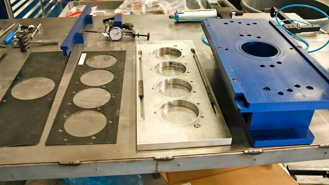
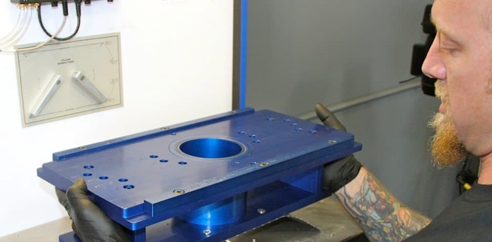
Here are the main tools to flow a cylinder head. On the right is the billet aluminum main adapter plate that bolts to the flowbench surface, on top of a rubber gasket (far left). On top of the big plate is another plate (second from right) that we’ll call the slider plate. It bolts to the cylinder head and sits/slides on the main adapter plate. A rubber O-ring seals the two. The 4-hole head gasket-like rubber gasket second from left goes between the head and slider for another airproof seal. The main adapter (below left) comes with several sets of different sized sleeves to match the cylinder bore of the engine block that the heads will be used on. This one is 4.030-inch. They have upper and lower O-rings for an airtight seal. The main adapter plate bolts to the bench, but it’s much easier to install a set of studs (below center) to save time and headaches. Note the gasket in place before the adapter is lifted in place and bolted down (below right). It just needs to be snug.
Expert Consultation
Curtis Boggs is a well-known cylinder-head specialist at Race Flow Development and is well-experienced in flow testing heads and evaluating the results. Following is EngineLabs ‘ one-on-one conversation with him:
EngineLabs: How important is it for an engine builder to own or have access to a flowbench, and why?
Curtis Boggs: Personally, when I’m involved in an engine build I want to have the most data possible. For an engine builder it really depends on the level he/she wants to work on in the cylinder head program. There’s a ton of good data for an engine builder with a flowbench. Once there’s a fair amount of data collected over several builds, it becomes easier to identify trends. A good cylinder head supplier would take some the pressure off of the typical engine builder to log flow numbers. However if the builder uses several different sources for heads it could help with data and identify trends if they did it themselves. It’s important to flow heads from different sources on the same bench with the same technique. Typically when one of my customers, or any engine builder, buys a flowbench, they learn some things very quickly. First, it doesn’t take the huge flow numbers people think to make power or win on Sunday, and a peak flow number isn’t the most important number. There’s a tremendous amount of data for an engine builder. I wouldn’t build anything without one.
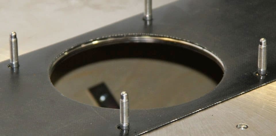
The main adapter (below left) comes with several sets of different sized sleeves to match the cylinder bore of the engine block that the heads will be used on. This one is 4.030-inch. They have upper and lower O-rings for an airtight seal. The main adapter plate bolts to the bench, but it’s much easier to install a set of studs (below center) to save time and headaches. Note the gasket in place before the adapter is lifted in place and bolted down (below right). It just needs to be snug.
EL: What can flow numbers tell you about a cylinder head’s performance?
Boggs: Flow numbers by themselves aren’t worth the weight most people give them. Yes, we can calculate the potential mass airflow through the engine, which is great data, but there’s much more data needed to make a good assessment. Port shape, geometry, chamber shape, velocity profiles etc., all play a significant roll in power. Experienced cylinder head engineers can tell some things from a flow chart—the curve can show a head with the port too big or a throat too small, things like that. What happens to the flow after the convergence point tells me a lot about a head.
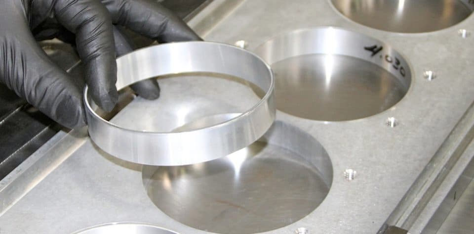
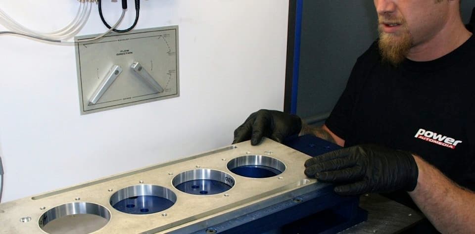
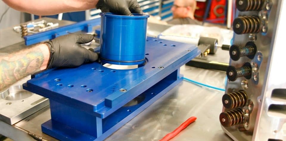
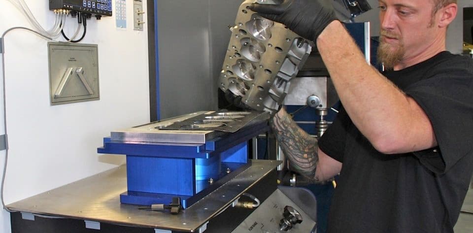
The head adapter (which we’ll call the slider plate) also has a selection of sleeves to match the bore size. We call it a slider plate since that’s what it does. It allows you to flow all four chambers on a head without unbolting and remounting it for each cylinder. PowerAutomedia tech Sean Goude marked both plates when the slider plate was perfectly placed over the main bore, to make sure that the flow numbers are accurate and also to speed testing.
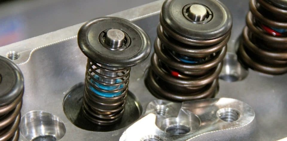
The valves are opened manually to test flow, so the valve springs must be changed to low-tension test springs, shown here on an iron head. Also, don’t forget the spark plug as you prepare the cylinder head. Otherwise there will be an obvious leak in the airflow. Make sure to use the “head gasket” when putting the cylinder head on the adapter plate. The head can be installed this way, or by bolting the slider plate to it first then lifting the assembly into place.
EL: Do you personally have a flowbench and how often do you use it?
Boggs: I’ve owned several flowbenches since I started in the mid ’70s, and have even built some. As an induction engineer I have to own one and use it on a daily basis.
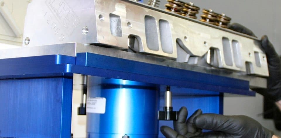
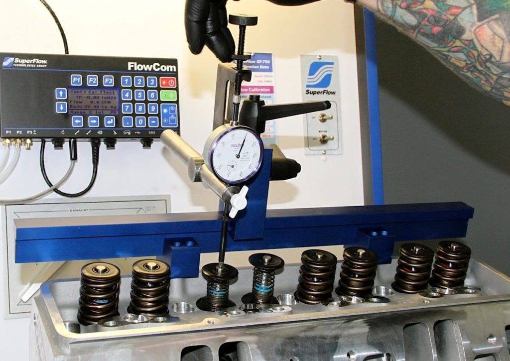
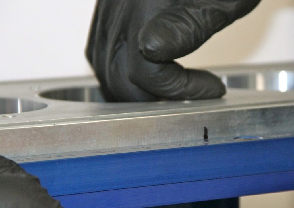
This hand screw tightens the slider plate when the chamber is lined up and ready to flow. Superflow includes this billet stand that bolts to the valve cover rail on the head. It mounts dial indicator used to indicate valve opening. During testing, the valve will opened via this dial indicator. Set it up then make sure it has enough stroke to open the valve to the highest point you want to test. In other words, if you have a .700” lift cam and want to test at that lift point, make sure the indicator has at least .700” travel. It’s a good idea to add another .050” for a safety margin. Goude likes to zero his indicator then run it down to .100” and back to zero to make sure it’s right.
EL: When using a flowbench for porting heads, are there different flow numbers you want to look for in applications for circle track, drag racing, street/strip, or the typical musclecar?
Boggs: Well again, it goes past just a CFM number. Too many people think the bigger the number the better, and it’s just not true all of the time! A great example here is the difference between a high rpm drag engine and a circle track engine. Drag engines typically can use larger ports, slower air speeds, and are run under a little more forgiving circumstances than a circle track engine. Big ports and big flow numbers typically don’t make fast lap times in circle track or road race cars. You have got to match the velocity profile of the head to the application. This will effect the peak flow number, so you should be using the flow bench with a velocity probe.
EL: Anything else you can say about flowbenches or airflow in general, beyond what has already been published in Engine Labs?
Boggs: Well, only that I have a reputation for saying that flow numbers don’t matter, and that couldn’t be farther from my intention. Flow numbers are very important—we are working on air pumps basically. However, the other things in a cylinder head like I mentioned earlier are as, if not more, important also. The biggest flow number doesn’t always win.
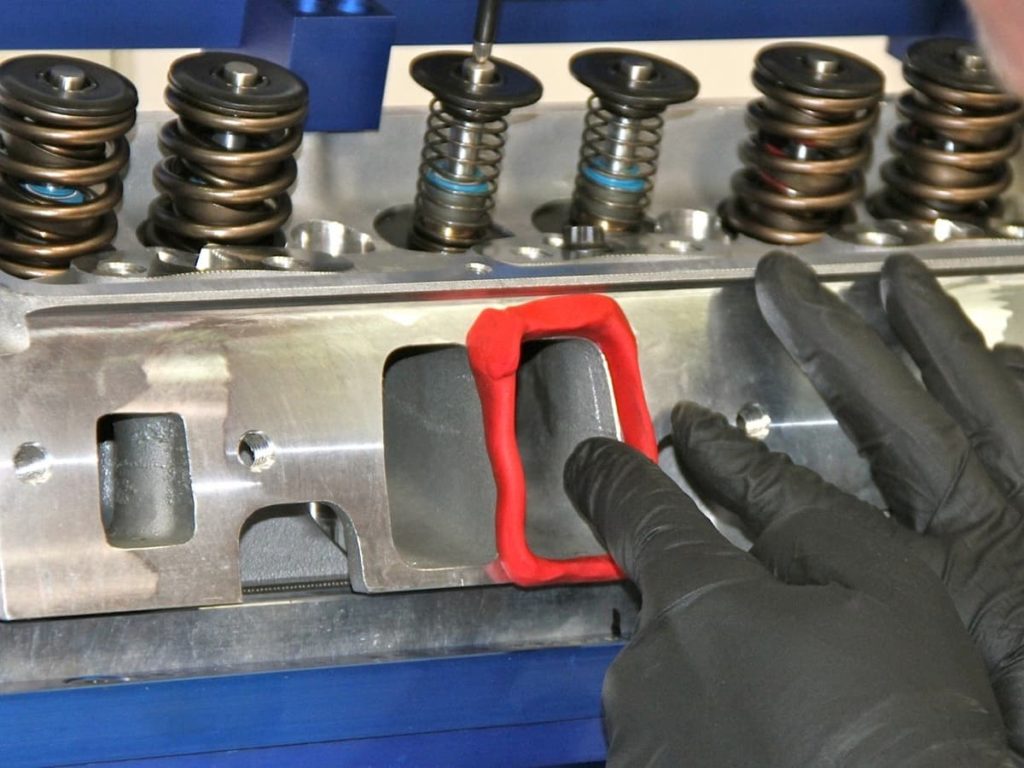
Before testing, utilize some form of radius to make a smooth transition into the port and an ensure a more accurate reading. Modeling clay works well, and aftermarket suppliers offer premolded attachments. The FlowCom system handles all the math, unlike the old days when readings had to be taken and computed by hand. But first, some settings have to be be made (see below) to the flow bench.
Shown from left: FlowCom touch screen, flow calibration table, flow direction handles and the light switch; Flow Calibration table showing six ranges of adjustment for flow (the closer the actual flow of the port is to these range maximums, the more accurate the resolution); Lever that sets the flow range; Levers to set the airflow direction.

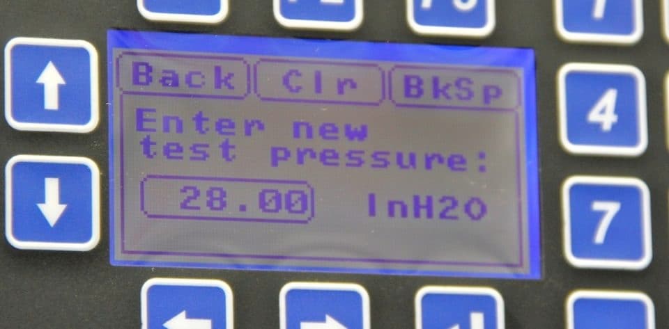
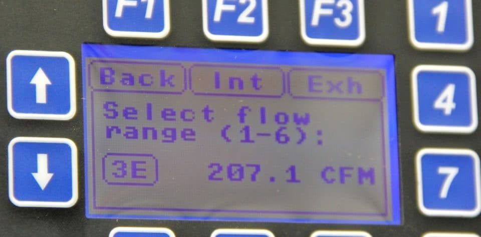
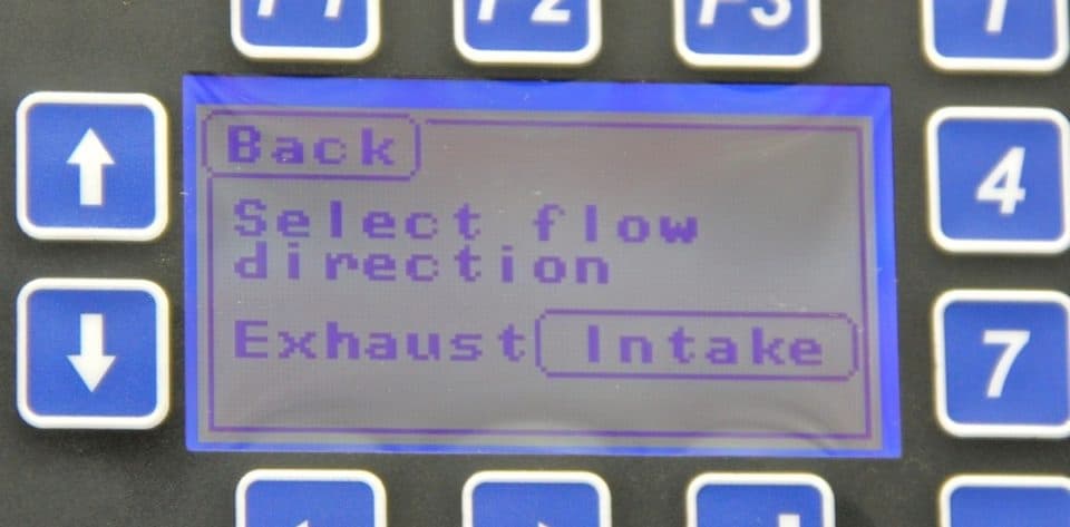
With the flow direction and range handles set, the remainder of preliminary information settings are entered in the FlowCom computer (above). The industry standard for flow testing is at 28 inches of water (below left) and the flow range, which was determined from the calibration table and set with the range handle, must be entered (center photo) along with the flow direction (right photo).
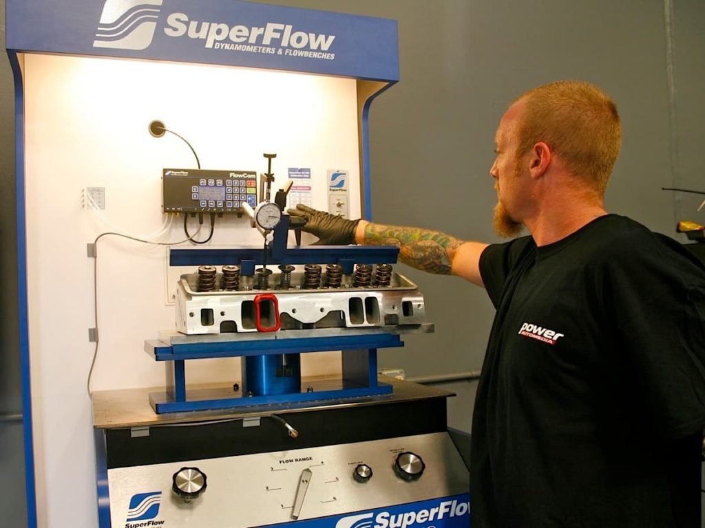
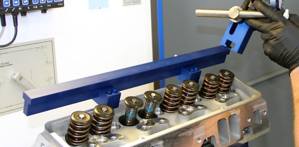
When everything is ready to go, hit the on/off switch and the bench starts working. Open the valve to the desired starting point (most use .050”) by turning the dial indicator adjustment screw (on top) to .050” as indicated on the dial, then continue with each increment after you log the results. A flowbench is loud, like the loudest vacuum cleaner you’ve ever heard, so you might want to consider earplugs.
One thing to watch out for is that the modeling clay doesn’t get sucked into the port. To test the exhaust side, you don’t need to flip the head around unless you want to flow it with a header in place. Just change flow direction and run through the computer again with the same routine as used on the intake side.
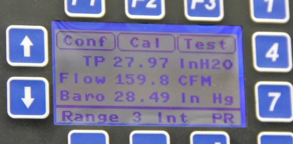
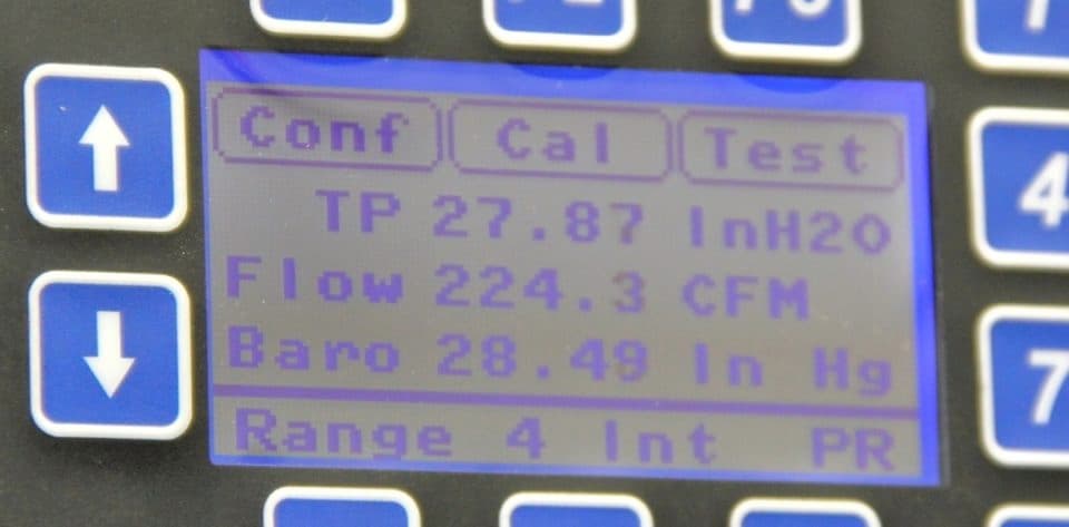
While the machine is flow testing, the cfm of airflow is shown on the computer screen after “Flow.” In these two cases the flow is 159.8 cfm and 224.3 cfm at valve openings of .300–inch and .600-inch, respectively. Simply jot down the numbers as you flow the head at different valve openings and then make the necessary comparisons to either confirm the airflow performance or help in cylinder head/intake manifold development.
